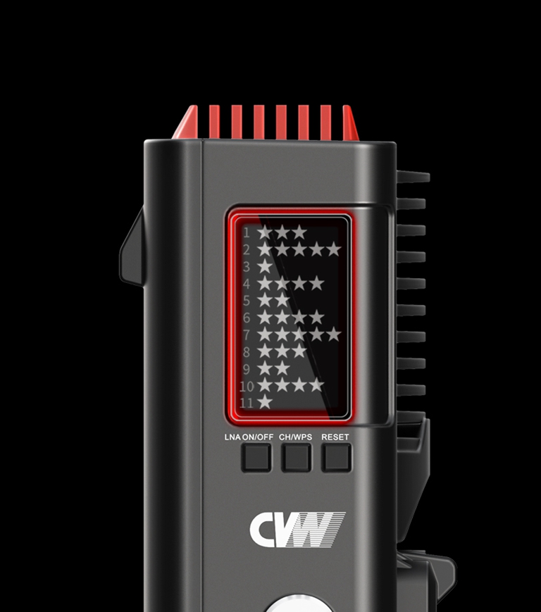
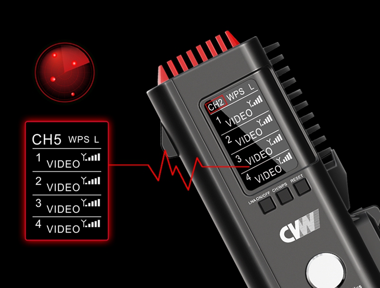
1. When one system is in use, it is recommended to set the channel at CH5-CH9. Because in most Wi-Fi coverage environments, the high and low frequency is mostly used, while somewhere between is rarely. The middle frequencies have low occupancy rates, which effectively avoids co-channel interference. Once the channel scanning function is enabled, it could quickly help to select the best possible channel from the available channel list.
2. When two systems are used simultaneously, the receivers must be placed at least 1 meter. Once the 80MHz operating mode is enabled, system one is set at CH5, and system two must be set at CH7, CH8, or CH9. It is recommended to keep them at least one channel apart. Once the channel scanning function is enabled, it could quickly help to select the best possible channel from the available channel list.
3. When multiple systems are used simultaneously, the receivers must be placed at least 1 meter apart. Once the 80MHz operating mode is enabled, system one is set at CH5, system two is set at CH7, and system three is at CH9. It is recommended to keep them at least one channel apart. Once the channel scanning function is enabled, it could quickly help to select the best possible channel from the available channel list.

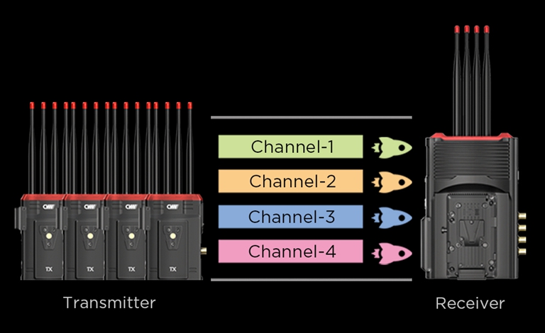
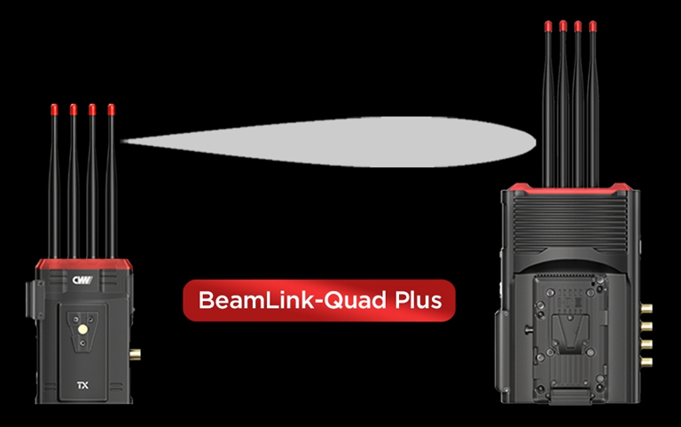
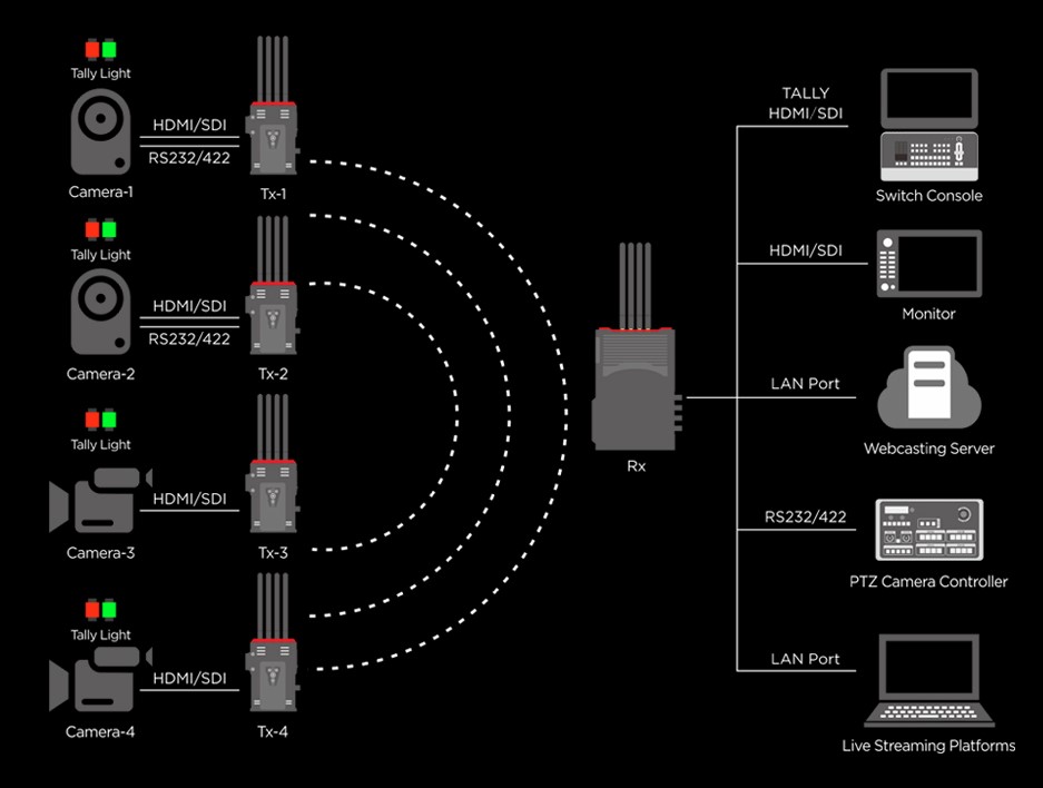
 Multi-camera wireless video transmission

 Designed for teleoperating the heavy equipment