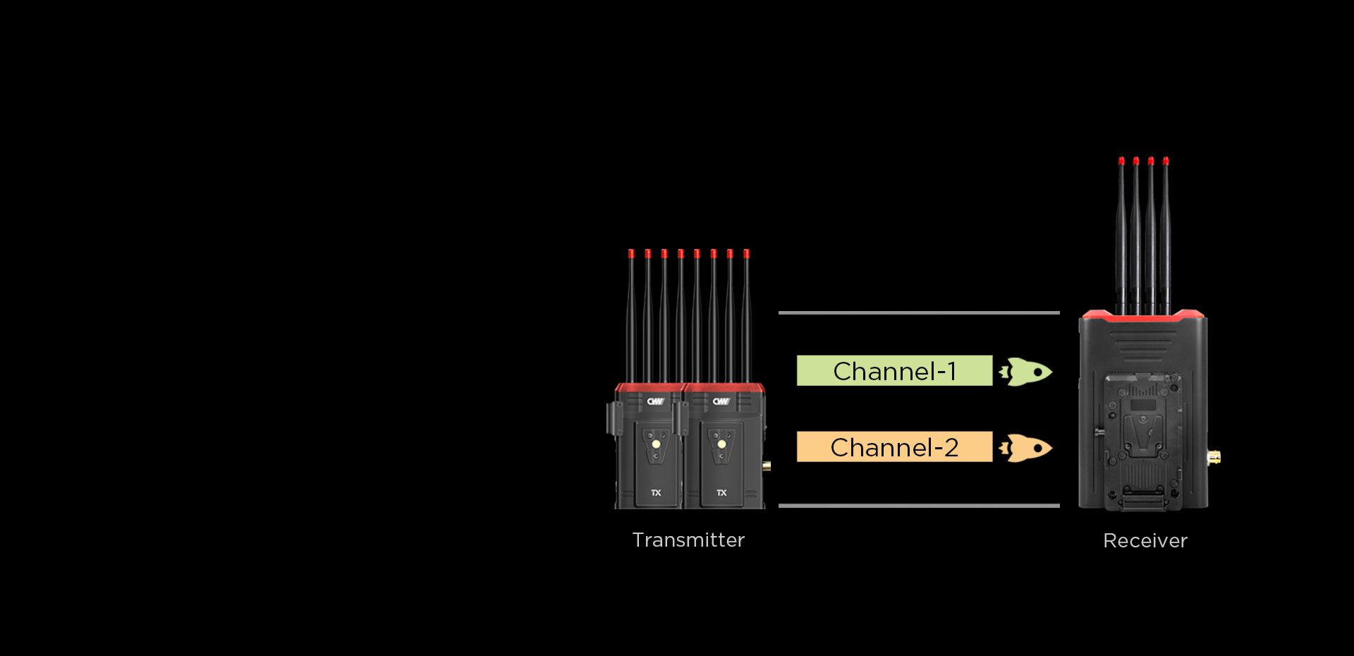
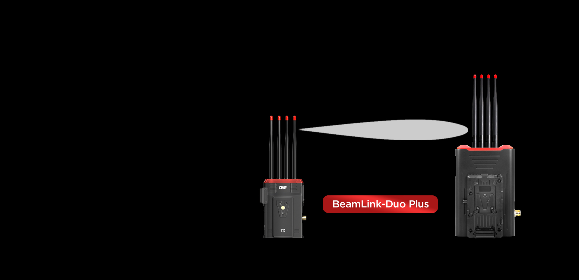
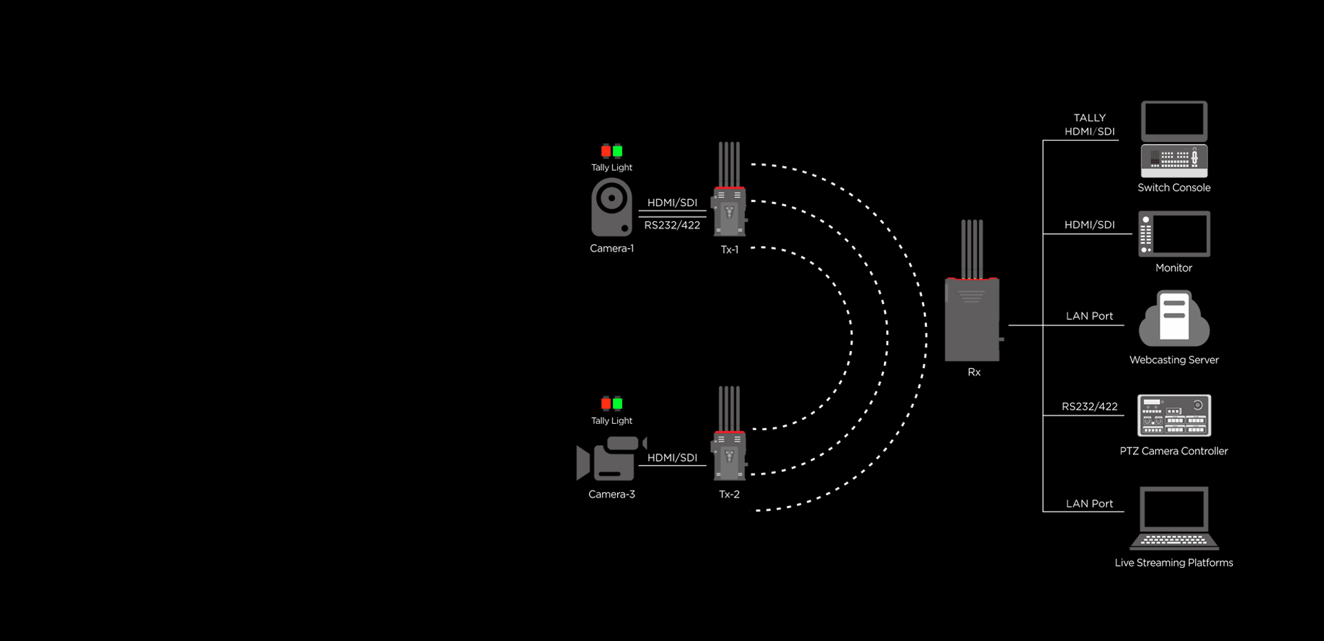
EN CN

BeamLink-Duo Plus

BeamLink-Duo Plus BeamLink-Duo Plus

2-Channel Wireless Video

Transmission

Two-channel transmission only occupies one

one wireless channel, significantly saving

spectrum resources.

Up to 1000 m/ 3200 ft of

transmission range (LoS)

The transmission distance can be extended

with the panel antenna.

H.265 CODEC technology

Compared with H.264 technology, H.265

technology offers higher color reproduction,

showcasing the whole image more colorful

and detailed.

Auto channel switch function

When there is a substantial wireless

interference, the receiver will scan the

available channels and switch automatically

to a channel with less interference.

4x4 MIMO and Beamforming

technology

* The direction of wirless beams is more concentrated.

* Wider coverage of wireless network.

* Stronger interference immunity.

Point-to-Point mode and RTSP

streaming mode

* HDMI+SDI+LAN port output simultaneously

* Point-to-Point mode or RTSP streaming mode

On-air indication - Tally

Wonderful compatibility

* Compatible with variety of cameras

* The RS232/422 data transparent transmission function

of the system can support the pan-tilt-zoom(PTZ) camera control.

Widely applied to different scenarios

Packing List


TX x2RX x1
Receiving Sensitivity/-70dBm
Transmission Power17dBm/
Frequency5.1-5.8GHz
Antenna Mode4×4 MIMO and Beamforming, 5dBi External antenna
Power Consumption10W13W
Operating Voltage7-17V7-36V
Video Resolution720p50/59.94/60,1080p23/24/25/25.97/30/50/59.94/60,1080i50/59.94/60
Audio FormatAAC
Transmission Range1000 m/ 3200 ft(LoS)
Product Size94(L)×39(W)×126(H)
Input/OutputHDMI x1, 3G-SDI x1, Tally x1, RS232/422 x1HDMI x2, 3G-SDI x2, Tally x1, RS232/422 x1, LAN Port x1
Wireless802.11n
Operating Power SupplyDC 12V/2ADC 12V/3A
Bandwidth40MHz
Temperature-10-50°C(Working);-20℃-+80℃(Storage)
VIDEOS
BeamLink-Duo Plus Video
BeamLink-Duo Plus Review Video
Tally Introduction Demo
PTZ Camera Control Demo
Tally Introduction Demo
QUESTIONS & ANSWERS
Q
BeamLink series products: Some ports correspond to brand that can be connected
A
1. TALLY Interface: Support docking with Yangming, SONY, Panasonic, Loran, Nga, BMD, Tianyitong, Zhongdiwei, Blue Torch and other brand switcher. According to customer demand, it is necessary to communicate with our sales staff in advance to provide TALLY model or TALLY interface of switcher, which is convenient to customize Tally cable for docking with switcher.
5.3. RS232/422 interface: Support to connect with SONY, Yang Ming, Panasonic, Kexuwell, Tomorrow, Weihaide and other brands PTZ camera, PTZ & controller, realize wireless control. According to customer demand, it is necessary to communicate with our sales staff in advance to provide RS232/422 interface or PTZ, PTZ & controller model, which is convenient to customize RS232/422 cable for docking with switcher.
Q
The WiFi connection light keeps flashing.
A

1. Check whether the other end of the device has power on; 2. Pairing operation; 3. Shorten the distance between the two devices; 3. If this condition still exists, please restart the device power.

Q
What format is the video stream coming out of the LNA port? Is it possible to change codes?
A

The output from the LNA interface is an IP video stream, which is decoded by a computer or a switch console.

Q
No sound during transmission.
A

Please check to see if the audio mode set by the transmitter is an external audio mode. If it is external audio mode, long press the MODE key for 3 seconds and release it to switch back to embedded audio mode.

Q
Extend the transmission range
A

You can use CVW panel antenna to extend its transmission range.  A panel antenna is a type of directional antenna, which can be used to extend the system’s transmission range, but the trade-off is that the panel antenna has a transmission angle of 45 degrees.

Q
The corresponding bandwidth to its working frequency
A

5.1-5.9GHZ (CH1-5.19G, CH2-5.23G, CH3-5.27G, CH4-5.31G, CH5-5.51G, CH6-5.55G, CH7-5.59G, CH8-5.63G, CH9-5.67G, CH10-5.755G, CH11-5.795G).

Q
The channel setting when you using one or more systems
A

1. When one system is in use, it is recommended to set the channel at CH5-CH9. Because in most Wi-Fi coverage environments, the high and low frequency is mostly used, while somewhere between is rarely. The middle frequencies have low occupancy rates, which effectively avoids co-channel interference. Once the channel scanning function is enabled, it could quickly help to select the best possible channel from the available channel list.

2. When two systems are used simultaneously, the receivers must be placed at least 1 meter. Once the 80MHz operating mode is enabled, system one is set at CH5, and system two must be set at CH7, CH8, or CH9. It is recommended to keep them at least one channel apart. Once the channel scanning function is enabled, it could quickly help to select the best possible channel from the available channel list.

3. When multiple systems are used simultaneously, the receivers must be placed at least 1 meter apart. Once the 80MHz operating mode is enabled, system one is set at CH5, system two is set at CH7, and system three is at CH9. It is recommended to keep them at least one channel apart. Once the channel scanning function is enabled, it could quickly help to select the best possible channel from the available channel list.

Q
The display is flickering green when the receiver outputs video signal to the monitor
A

The HDMI cable has not been firmly plugged in the transmitter or receiver’s HDMI port or has not been firmly plugged in the camera’s HDMI port. Please unplug and plug the HDMI cable or change it to another HDMI cable.

Q
No video output when connecting a receiver to a switch console or monitor
A

Please confirm if the transmitter and receiver’s OLED screen displays the signal icon and the word ”VIDEO”. If there is no signal icon, it indicates that the network is not connected. please refer to the first problem’s solution of troubleshooting. If there is a signal icon, but the transmitter’s OLED screen does not display the word “VIDEO”, please check the video source and the connected SDI/HDMI cable. If the transmitter and receiver have a signal icon and a word “VIDEO”, but the switch console displays nothing, please check the SDI/HDMI cable that is connected to the switch console, and change the camera’s video output resolution to 1080i50 or 720p50, then test it. In addition, connect the receiver to other monitor with the SDI/HDMI cable to test them.

Q
The monitor displays mosaic or lag
A

  1. Within a 300 meters range, LNA mode is set at low gain mode (OLED screen displays the letter “L”, meaning that it is in low gain mode).
  2. When multiple transmitters are used simultaneously, please ensure that the transmitters are at least 1 meter apart.
  3. The transmitter is set up on a camera, it should be set up at 1.5-2 meters above the ground, and the cameraman’s body should not obstruct the antennas. The receiver should be set up at least 2 meters above the ground, and the antennas are fan-shaped, and each has a clear line of sight.
  4. The working channel is set between CH5-CH9.
  5. In a range exceeding 300 meters or when needing to transmit a signal through walls, please set the transmitter and receiver to high gain mode.
  6. If multiple systems are used simultaneously, please keep their receivers at least 2 meters apart.
  7. If a wireless broadcasting and communication system is used on set, please keep the broadcast and communication host and the CVW receiver at least 2 meters apart.

Q
A black screen is displayed on the monitor via receiver output
A

Suppose the monitor displays a black screen through receiver output after switching the video source’s video resolution. Please unplug and plug the transmitter or receiver’s HDMI cable. If unplugging and plugging an HDMI cable does not make the system work normally, please restart the transmitter and receiver.

Q
The transmitter and receiver are unable to establish a connection
A

1. In short-distance situations, please ensure that the transmitter and receiver’s antennas are already fully installed, then you must place them 5 meters. With LNA mode being set at low gain mode, (OLED screen displays the letter “L”, meaning it is in low gain mode) and when multiple transmitters are used simultaneously, please ensure that the transmitters are at least 1 meter apart.

2. In long-distance situations, the transmitter is set up on a camera or handle, it should be set up at 1.5-2 meters above the ground, and the cameraman’s body should not obstruct the antenna’s cylinder. The receiver should be set up at least 2 meters above the  The transmission is optimal when the antennas are arranged to be fan-shaped and have a clear line of sight. With LNA mode being set at high gain mode (OLED screen does not display the letter “L”, meaning it is in high gain mode) and when multiple transmitters are used simultaneously, please ensure that the transmitters are at least 2 meters apart.

3. Please set the working channel between CH5 to CH9.

4. Re-pairing the transmitter and receiver. A. Long press the WPS button for 3 seconds. “WPS” will be displayed on the transmitter and receiver’s OLED screen. When they build the connection successfully, the signal strength will be showed. B. If they failed to pairing, please change to other environments to try.

Q
Two ways for HDMI, SDI and LAN port outputing
A

1. Examine whether all the antennas are being fan shape.


2. Examine whether the power adapter or battery input meets the product’s specification requirements.


3. Examine the product whether it can be started up normally; whether the screen can display normally.


4. Examine whether the system channels are corresponding.